1-208-754-4884

What Are the Best Automated Valves in 2026?
Choosing the best Automated Valves in 2026 means looking beyond price and headline specifications. A valve must suit the medium, pressure, temperature, flow requirements, and control system. It also has to work reliably in the conditions found on site: vibration near a pump, moisture around an outdoor actuator, or repeated cycles on a production line. Small mismatches can become expensive maintenance problems.
A useful selection principle is: “Match the valve to the process first; add smart control only when it solves a real operating need.” This is an original editorial quotation, not a verified statement from a named industry expert. A real expert’s name and exact words should be confirmed before publication. That distinction matters. Buyers deserve recommendations grounded in manufacturer documentation, application data, and practical operating experience—not invented endorsements.
This guide compares valve types, actuation options, control features, and maintenance needs. It considers where electric, pneumatic, and hydraulic actuation may fit, while recognizing that no single design suits every plant. Some facilities need precise positioning. Others need dependable on-off service and straightforward repairs. The “best” choice depends on the job.
We will also examine what specifications can hide: response time under load, actuator protection, service access, and compatibility with existing controls. A careful comparison can narrow the shortlist. It cannot replace reviewing the actual process conditions with qualified engineering staff.
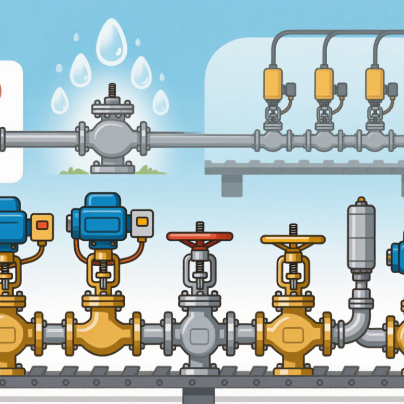
Table of Contents
[Hide]
How Automated Valves Work and Where They Are Used
Automated valves control the movement of liquids or gases without requiring someone to turn a handle by hand. A valve body contains a moving part, such as a ball, disc, or plug. An actuator moves that part when it receives an electrical or pneumatic command. Many systems also use position feedback to check whether the valve reached its target. That is the basic control loop. Small movements matter.
Valve design affects how it handles pressure, flow, and maintenance. Ball valves can open or close quickly, while globe valves allow more precise flow adjustment in many applications. Butterfly valves are often used in larger pipes where space matters. Diaphragm valves can suit some services that need a barrier between the fluid and moving components. These are general patterns, not guarantees; material compatibility and operating conditions still matter.
Automated valves appear in water treatment, building heating and cooling, irrigation, and process plants. A technician might set a valve to maintain a tank level or adjust chilled-water flow as demand changes. The right choice depends on the fluid, temperature, pressure, response time, and available power. Fail-safe behavior deserves attention too: should the valve close, open, or hold position during a power loss? There is no universal answer. Installation details and periodic checks can be overlooked, yet a misaligned actuator or sticking valve can undermine an otherwise well-designed system.
What Are the Best Automated Valves in 2026? — How Automated Valves Work and Where They Are Used
| Automated valve type | How it works | Common uses | Key advantages | Points to consider | Best fit when… |
|---|---|---|---|---|---|
| Electric quarter-turn Typically paired with a ball or butterfly valve |
An electric motor turns the valve stem through a quarter-turn to open or close the valve. Some actuators support intermediate positioning and modulating control. | Water and wastewater systems, HVAC, building services, and general process piping. | Does not require a compressed-air supply; can be integrated with control systems for remote operation and position feedback. | Operation may be slower than pneumatic actuation. Confirm power availability, enclosure protection, duty cycle, and required torque. | Electrical power and control signals are available, and a practical installation without instrument air is preferred. |
| Pneumatic quarter-turn Typically paired with a ball or butterfly valve |
Compressed air drives a rack-and-pinion or scotch-yoke actuator to rotate the valve. Spring-return designs can move to a defined position when air supply is lost. | Industrial process lines, chemical plants, water treatment, and applications requiring frequent or quick operation. | Often provides rapid operation and a simple route to spring-return fail positioning; pneumatic actuators are widely used in industrial environments. | Needs a reliable, properly sized air supply and suitable air treatment. Check actuator torque against valve requirements and operating conditions. | Instrument air is available and fast cycling or a defined response to loss of air is important. |
| Electric linear Typically paired with a globe or other linear-motion valve |
An electric motor and drive mechanism move the valve stem linearly. The actuator can be configured for open/close service or, when designed for it, position control. | Heating and cooling circuits, process flow control, and systems that need gradual adjustment rather than a simple quarter-turn. | Allows controlled stem movement without compressed air and can support repeatable positioning with compatible controls. | Check thrust, stroke, positioning accuracy, response time, and whether the actuator is rated for the required modulation duty. | Linear stem movement and electrically commanded positioning suit the process and its control system. |
| Pneumatic linear Typically paired with a globe or diaphragm valve |
Air pressure moves a piston or diaphragm to position the valve stem. A spring-return arrangement may provide a defined valve position if air pressure is lost. | Process control in chemical, food and beverage, pharmaceutical, and utility systems, subject to valve and material selection. | Suitable for continuous control when paired with an appropriate positioner; spring-return options can provide a specified fail action. | Requires instrument air. The valve trim, actuator, and positioner must be selected for the fluid, pressure, temperature, and control range. | Reliable pneumatic control is available and accurate modulation is required. |
| Solenoid-operated valve Commonly a compact on/off valve |
An energized coil creates a magnetic force that moves a plunger or pilot mechanism. Direct-acting and pilot-operated designs have different pressure and flow requirements. | Small-bore fluid or gas circuits, equipment skids, appliances, and automatic dosing or utility services. | Compact and electrically switched; useful for automatic on/off control where the valve size and operating conditions suit the design. | Verify fluid compatibility, voltage, pressure range, flow capacity, and whether a pilot-operated design needs a minimum pressure differential. | A compact electrically controlled on/off valve is needed and the required flow and pressure fall within the valve’s specifications. |
| Electro-hydraulic Hydraulic actuator controlled by an electrical signal |
An electric control system operates hydraulic pressure that moves the actuator, producing linear or rotary valve motion. | Large valves, high-force duties, and installations where hydraulic actuation is already part of the system. | Can deliver high actuation force in demanding applications and can be integrated with electrical control and feedback. | System design is more involved than a basic electric actuator; assess hydraulic power, maintenance, leakage control, and fail-position needs. | High actuator force is required and the installation can support the hydraulic equipment and maintenance requirements. |
Selection note: There is no single best automated valve for every service. Match the valve body and actuator to the fluid, pressure, temperature, flow requirement, control method, operating frequency, available utilities, and required response to power or air failure. Confirm all limits against the selected valve and actuator specifications.
Related Posts
-

Ultimate Guide to Selecting the Right Automated Valves for Your Industry
-

Evaluating Automated Valves: A Comparative Analysis of Performance Metrics and Efficiency in Industrial Applications
-
2026 How to Choose the Right Automated Valves for Your System?
-
Discover Innovative Control Valve Types at the Upcoming Canton Fair in Guangzhou
-
Essential Guide to Selecting Top Manufacturers: Solutions for Best At Control Valves Procurement
-
Understanding the Different Types of Control Valves: A Comprehensive Guide