
1-208-754-4884

7 Tips for Choosing a Millimeter Wave Power Amplifier

Choosing a Millimeter Wave Power Amplifier is not just a matter of finding the highest output-power rating. The right unit must suit the frequency band, signal type, operating environment, and measurement setup. A small mismatch can show up as extra heat, unstable readings, or less usable power at the antenna. Details matter.

Start with the actual frequency range, then check output power, gain, and linearity against your application. For a modulated signal, peak power alone may not describe real performance; compression and distortion figures can matter just as much. Review the datasheet conditions carefully, including temperature, supply voltage, and test frequency. Numbers measured under different conditions are not always comparable. That is easy to overlook.

The seven tips in this guide focus on practical selection, from bandwidth and efficiency to cooling, connectors, and support documentation. Look for test data that matches your intended operating range, and consider how the amplifier will be mounted and connected. A tiny connector or a long cable can affect results at millimeter-wave frequencies. Bench estimates can also miss installation realities, so leave room to verify performance in your own setup. It is not always a clean tradeoff: more power may bring higher heat, cost, or power demand. Compare the complete system, not one impressive specification. A careful choice should make performance predictable, not merely attractive on paper.
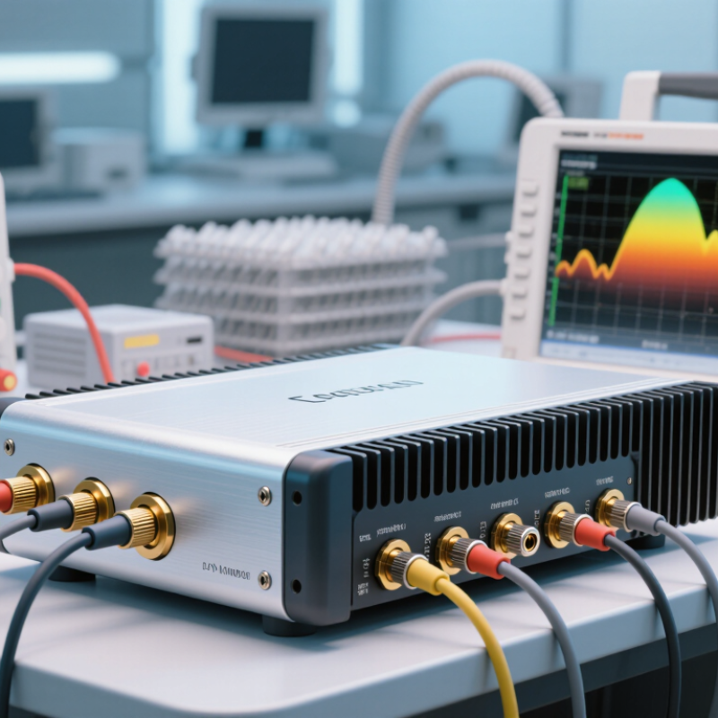
7 Tips for Choosing a Millimeter Wave Power Amplifier

Define the Application and Operating Requirements

Start with the actual job the amplifier must perform. Is it driving a radar antenna, a short-range wireless link, or a lab test fixture? Each use places different demands on bandwidth, output power, and signal quality. Be specific. Write down the frequency range, modulation type, and required channel bandwidth, not just “millimeter wave.” A 28 GHz design, for example, may need to remain linear across a wide modulated signal, while a pulsed system may prioritize peak power and pulse duration.

Define power at the point that matters. A cable, connector, or waveguide transition can reduce the power reaching the load, so distinguish amplifier output from delivered power. Also record whether the requirement is peak or average. That distinction is easy to miss. Specify acceptable error vector magnitude or adjacent-channel leakage when signal fidelity matters, and check these values across the intended bandwidth. Note the duty cycle, ambient temperature, available supply voltage, and cooling limits. A unit that meets its power target on a cool bench may behave differently inside a compact enclosure. Leave some margin, but do not guess excessively; overly generous requirements can narrow suitable choices without improving the application. Recheck the assumptions against the real setup. Small omissions add up.

7 Tips for Choosing a Millimeter-Wave Power Amplifier: Define the Application and Operating Requirements

Frequency affects wavelength, antenna dimensions, propagation, and system design. When defining your application, specify the operating band along with required output power, bandwidth, linearity, efficiency, and thermal limits. Wavelength values shown are calculated from the speed of light in free space.

Match the Frequency Range, Output Power, and Gain

A millimeter-wave power amplifier should cover the actual operating band, not just its center frequency. Start with the lowest and highest frequencies your system will use. Then check whether gain and output power remain acceptable across that span. A unit rated for a wide band may still show a sharp performance dip near one edge. Check the units. Confirm that specifications use the same frequency range you need.

Power figures need context. Look for saturated output power and, where available, output power at a stated compression point. For modulated signals, leave headroom so peaks are not clipped. Include losses from cables, connectors, and filters when estimating power at the antenna or device input. That gap matters. A room-temperature rating may also shift when the amplifier warms during operation.

Gain determines how much drive the amplifier needs, but more gain is not always better. Compare gain across the band, then check whether it is flat enough for your signal. A gain ripple can complicate calibration, while excessive gain may make the chain harder to control. Review the test conditions, including temperature and input level. Datasheets do not always make comparisons easy, so verify uncertain figures with the supplier or a bench measurement before committing to a design.

Assess Linearity, Noise, and Power Efficiency

For a millimeter-wave power amplifier, check linearity at the intended bandwidth and output back-off, not only at saturation. 3GPP TS 38.104, Release 17, sets a 3.5% EVM limit for 256-QAM in applicable base-station cases; verify the band and equipment class before treating it as a pass/fail target. Numbers need context. Measure EVM, AM-AM and AM-PM distortion, and adjacent-channel leakage with the intended modulated waveform. A clean continuous-wave trace can hide distortion that appears under real signal conditions.

Noise needs careful interpretation. At 290 K, thermal noise density is about −174 dBm/Hz; integrated noise rises with measurement bandwidth. Request output-noise measurements across the occupied band, and compare test conditions using 3GPP TS 38.141-1 conformance procedures where applicable. A low noise figure alone does not guarantee a clean transmitted signal. Check power-added efficiency at the backed-off operating point, then repeat after the amplifier warms up. Measure it warm. Efficiency often falls when linearity improves, so compare units at the output power your system actually needs. Datasheet figures can still mislead: fixture loss, temperature, and waveform choice all change the result. I would question any single headline number without those details.

Check Thermal Management, Stability, and Integration

A millimeter-wave power amplifier can meet its output target on a bench and still struggle inside a compact enclosure. Heat builds fast. Check the thermal path from the device package to the board, chassis, and surrounding air. A warm chassis, blocked vent, or thin interface pad can raise junction temperature during sustained operation. Review derating curves at the expected ambient temperature, not just the room-temperature rating. Leave room for airflow or a conductive spreader, then measure temperature after the unit reaches steady state. Small enclosures punish assumptions.

Stability deserves equal attention. Ask for stability data across the intended frequency range and examine behavior outside the operating band. During integration, inspect the bias network, decoupling, grounding, and transitions between the amplifier and antenna. At millimeter-wave frequencies, a few millimeters of trace or a poor connector launch can alter matching. Simulate with the intended board stack-up, then test the assembled board with calibrated equipment. A first layout may look tidy, yet parasitic coupling can still surprise you. I would not trust a clean simulation alone. Check gain, output power, and temperature under realistic signal and duty-cycle conditions. Small changes in the enclosure can shift results, so leave time for another measurement.

7 Tips for Choosing a Millimeter Wave Power Amplifier — Check Thermal Management, Stability, and Integration
# Selection Dimension What to Check Practical Evaluation Why It Matters
1 Frequency coverage Operating band, usable bandwidth, and gain variation across the band. Compare the amplifier’s specified frequency range with the full signal band, including any required guard band. Review gain and output-power data across frequency, not only at the center frequency. Millimeter-wave performance can change noticeably with frequency, and a nominal center-frequency result may not represent operation at band edges.
2 Output power and linearity Saturated output power, output power at the required linearity, gain compression, and applicable modulation metrics. Match the specification to the signal’s peak-to-average power ratio and required EVM or adjacent-channel performance. Do not treat saturated power as the expected linear operating power. The power amplifier may need output back-off to preserve signal quality, reducing the power available for the link.
3 Thermal management Power dissipation, thermal resistance, allowed case or baseplate temperature, and maximum junction temperature. Estimate dissipation from the intended bias and RF operating conditions. Check the datasheet’s thermal definitions and plan for a suitable heat spreader, mounting interface, and airflow or cold plate if needed. Excess junction temperature can reduce reliability and performance. Thermal limits and measurement conditions vary by device, so use the specific datasheet rather than a generic temperature assumption.
4 Stability and oscillation risk Stability information over frequency, bias conditions, source and load mismatch, and recommended stabilization measures. Review stability data beyond the intended signal band where available. Verify the complete circuit, including bias networks and interconnects, under realistic source/load impedances and operating conditions. A power amplifier can become unstable outside its nominal band or when connected to a different load or layout than the evaluation setup.
5 Impedance matching and interfaces RF input/output impedance, matching requirements, connector or launch type, and any reference-plane definition. Confirm the intended system impedance and identify whether matching is integrated or must be provided externally. Check calibration and reference-plane details when comparing measured data. At millimeter-wave frequencies, small discontinuities and mismatched reference planes can materially affect measured gain, return loss, and delivered power.
6 Biasing and power supply Required supply rails, current draw, sequencing, gate or control voltages, and bias decoupling guidance. Check startup and shutdown requirements, supply tolerance, current capacity, and the recommended bias network. Include supply losses and transient behavior in the design review. Incorrect bias sequencing or inadequate supply design can affect performance and may damage the device.
7 Mechanical and system integration Package dimensions, mounting and grounding, RF transitions, control interfaces, and environmental requirements. Check the mechanical drawing and assembly guidance against the board or module layout. Evaluate grounding, thermal contact, cable or waveguide transitions, and the intended operating environment. A suitable electrical part may still be difficult to use if its package, thermal path, or RF interfaces do not fit the system design.

Compare Specifications and Verify Performance Through Testing

7 Tips for Choosing a Millimeter Wave Power Amplifier

Compare amplifiers at the exact frequencies, bandwidths, and power levels your link will use. Two units with similar headline output can behave differently near band edges. Check gain flatness, saturated output, P1dB, and linearity, not just peak power. For modulated signals, ask for EVM or ACLR results at a stated output level. Conditions matter.

Look for data across supply voltage, case temperature, and duty cycle. Efficiency and thermal resistance help predict whether a compact housing can shed heat. Confirm stability and input and output matching across the intended band. Then test the actual unit. Use calibrated instruments and suitable millimeter-wave cables or waveguide. Account for cable loss and connector repeatability; even small measurement errors can distort comparisons.

Run the same waveform and bandwidth planned for the system, then repeat at hot and cool conditions. Test under load. Record output power, gain, current draw, and spectral quality together. A datasheet cannot capture every fixture, mismatch, or installation detail. Your first test setup may also be imperfect, so document measurement uncertainty and refine the setup before making a final comparison.