1-208-754-4884

Why Choose a Hydraulic Pressure Control Valve?
Hydraulic systems rely on controlled pressure to move loads smoothly and protect connected components. A Hydraulic Pressure Control Valve helps regulate, limit, or direct pressure according to the circuit’s design. In a workshop, that control can mean a lift table rises steadily instead of jolting, or a pump avoids pressure beyond its intended operating range. Small changes matter.
Choosing a valve starts with the application, not just the connection size. Check the required pressure range, flow rate, fluid type, operating temperature, and port configuration. A relief valve limits excessive system pressure; a reducing valve maintains lower pressure in a branch. They are not interchangeable. This distinction is easy to overlook.
Installation conditions matter too. Contamination, incorrect adjustment, or an undersized valve can cause unstable operation, excess heat, or premature wear. Even a correctly selected model may perform poorly if the system’s actual flow differs from the design assumptions. That deserves a second look. Review the manufacturer’s specifications, confirm compatibility with the pump and actuator, and follow appropriate setup and maintenance procedures. If the application is unusual, consult a qualified hydraulic specialist rather than guessing at a pressure setting. A careful choice can support reliable performance, but no valve compensates for a poorly designed circuit.
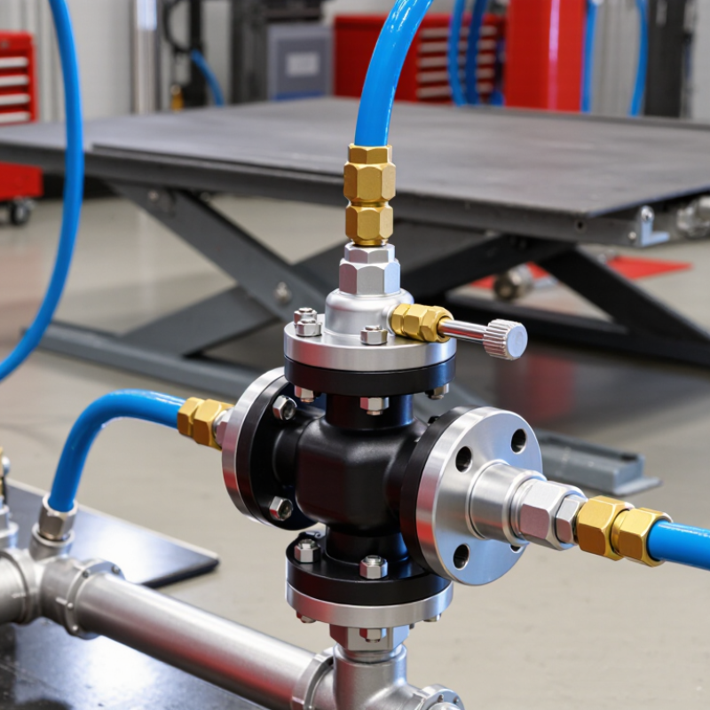
Table of Contents
[Hide]
What a Hydraulic Pressure Control Valve Does
Why Choose a Hydraulic Pressure Control Valve?
What a Hydraulic Pressure Control Valve Does
A hydraulic pressure control valve manages pressure in a fluid-powered circuit. It can limit peak pressure, maintain a selected pressure, or direct flow when a set pressure is reached. In a relief valve, excess fluid returns to the reservoir when pressure rises above its setting. That helps protect pumps, hoses, cylinders, and other components from overload.
It also affects how a machine behaves. A correctly adjusted valve can help a cylinder lift a load steadily or allow one circuit to operate before another. The setting must match the system’s working pressure and component ratings; one number does not suit every machine. Small details count. Oil temperature, contamination, and worn seals can change performance over time. A valve that opens too early may reduce available force, while one set too high may leave parts exposed to damaging pressure. Not every fault comes from the valve, either. Check the pump, fluid, and connected components before changing adjustments. A pressure gauge and the equipment’s service specifications provide a safer basis for diagnosis than guesswork. That extra check matters.
| Valve Type | What It Controls | How It Works | Typical Application | Why Choose It |
|---|---|---|---|---|
| Pressure Relief Valve | Maximum system pressure | Opens when pressure reaches its setting, allowing fluid to flow to a low-pressure path such as the tank. | Protecting a pump and hydraulic circuit from excessive pressure. | Helps limit pressure-related damage. The setting must be suitable for the system’s components and design. |
| Pressure-Reducing Valve | Pressure in a branch or downstream circuit | Typically remains open and throttles flow when downstream pressure reaches its setting, maintaining a lower pressure in that circuit. | Supplying a lower-pressure actuator or auxiliary circuit from a higher-pressure supply. | Allows different parts of one hydraulic system to operate at different pressure levels. |
| Sequence Valve | The pressure at which a secondary operation begins | Opens at a set inlet pressure to permit flow to a secondary circuit; many designs include a check valve for reverse flow. | Operating two hydraulic functions in a pressure-dependent order. | Can coordinate circuit functions without relying only on timing, provided the circuit is designed for pressure-based sequencing. |
| Unloading Valve | Whether pump flow is delivered to the working circuit or diverted at low pressure | When its control condition is met, it directs pump flow to the tank or another low-pressure path. | Unloading a pump in systems that use an accumulator or have periods of low demand. | Can reduce the pressure load on a pump during suitable operating periods; system layout and control conditions matter. |
| Counterbalance Valve | Load-induced pressure and movement on an actuator | Maintains back pressure and meters out fluid to help control an overrunning load; pilot pressure may assist opening in pilot-operated designs. | Controlling a suspended or overrunning load, such as a hydraulic cylinder supporting a raised mechanism. | Helps prevent uncontrolled load movement and supports stable motion when correctly selected and installed. |
Related Posts
-

Evaluating Automated Valves: A Comparative Analysis of Performance Metrics and Efficiency in Industrial Applications
-
5 Reasons Why Our Best Elevator Valve Outperforms Competitors by 35% in Efficiency
-
What Are the Best Automated Valves in 2026?
-

How to Control Hydraulic Systems for Optimal Performance?
-
Understanding the Different Types of Control Valves: A Comprehensive Guide
-
Maximize Your Global Reach with Central Valves at the Record Breaking 2025 Canton Fair