1-208-754-4884

What Is a Control Valve and How Does It Work?

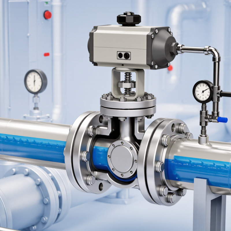
A control valve regulates fluid flow by changing the opening inside a pipeline. It may control water, steam, gas, oil, or chemical mixtures. In practical operation, a valve responds to a signal from a process controller. That signal moves an actuator, which positions the valve plug, ball, or disc.

The operating principle is straightforward. A sensor measures pressure, temperature, level, or flow. The controller compares that reading with the desired setpoint. It then sends a corrective signal to the actuator. The actuator moves the valve stem, adjusting the flow area. A smaller opening usually reduces flow, while a larger opening allows more fluid to pass. Sometimes, the response is not perfectly linear.

This article explains how Control Valves work, including their main parts, operating methods, and common applications. It also considers sizing, pressure drop, cavitation, leakage, and actuator selection. These details matter on a real plant floor. A poorly sized valve can hunt continuously, create noise, or damage nearby equipment. Engineers often verify performance against recognized practices, including IEC 60534 guidance, manufacturer data, and site test results. Field experience remains important, though. A clean calculation cannot reveal every vibration, temperature change, or installation mistake. Small details count. Understanding these limits helps readers evaluate valve performance safely and make more reliable decisions.
What Is a Control Valve and How Does It Work?

Control Valve Fundamentals: IEC 60534 Defines Flow Capacity Through Cv

What Is a Control Valve and How Does It Work?

A control valve regulates fluid flow by changing the opening between its plug and seat. An actuator moves the valve in response to a control signal. This action adjusts pressure, temperature, level, or flow inside a process line. Small position changes can produce noticeable results.

IEC 60534 provides recognized methods for evaluating valve flow capacity. The key value is Cv, which describes how much water can pass through a valve under a defined pressure drop. In common practice, one Cv represents one US gallon per minute with a one psi pressure differential. Engineers use Cv with flow rate, pressure, temperature, and fluid density to select a suitable valve size.

The calculation is not just a catalog exercise. A steam valve and a cooling-water valve may require very different Cv values. Cavitation, flashing, excessive noise, and poor controllability can appear when the pressure conditions are misunderstood. Field checks often reveal another problem: the valve is correctly sized, but the actuator cannot provide stable positioning. That detail is easy to miss.

A useful sizing review compares the calculated Cv with the valve’s available range. Oversizing may cause the valve to operate nearly closed. Undersizing can create excessive pressure loss. The result may look acceptable on paper, but real piping conditions deserve another review.

Key Components: Body, Trim, Actuator, Positioner, and Feedback Devices

A control valve regulates fluid flow by changing the passage through a pipeline. Its body contains pressure and directs the medium safely. Inside, the trim, including the plug, seat, and stem, controls flow accuracy. Small wear marks on a seat can create noticeable leakage.

The actuator supplies movement. It may use pneumatic, electric, or hydraulic energy. The positioner converts the control signal into precise actuator motion. Feedback devices then report stem position, pressure, or travel to the control system. This creates a correction loop. Fast response matters, but excessive speed can cause instability. In field service, a slow valve is not always a faulty valve.

Selection should match pressure, temperature, fluid chemistry, and required flow range. IEC 60534 provides widely used guidance for industrial control valve sizing and testing. The International Energy Agency reported that industry consumed about 37% of global final energy in 2022. Better control can therefore support meaningful efficiency improvements, although valve performance alone cannot solve plant-wide losses. The U.S. Department of Energy also identifies process control and maintenance as practical industrial efficiency opportunities. A useful inspection checks calibration, air supply, trim damage, and feedback signals together. Diagrams look clean. Real installations rarely do.

What Is a Control Valve and How Does It Work? - Key Components: Body, Trim, Actuator, Positioner, and Feedback Devices

Component Primary Function How It Works Common Materials Typical Inputs or Signals Key Selection Factors Typical Failure Symptoms
Valve Body Contains the pressure boundary and directs fluid through the valve. The body provides the inlet and outlet connections while the internal passage changes the flow path as the valve opens or closes. Carbon steel, stainless steel, alloy steel, ductile iron, or corrosion-resistant alloys. Process pressure, temperature, flow rate, and fluid composition. Pressure class, temperature rating, connection type, corrosion resistance, and required flow capacity. External leakage, wall thinning, cracking, abnormal vibration, or excessive pressure drop.
Trim Controls the actual flow area inside the valve. The plug, seat, cage, disc, ball, stem, and related internal parts regulate flow by changing the opening between the inlet and outlet. Stainless steel, hardened alloys, tungsten-carbide coatings, and engineered polymers for selected services. Stem movement or rotary shaft movement generated by the actuator. Flow coefficient, leakage class, cavitation risk, flashing, erosion, noise, and compatibility with the process fluid. Unstable flow, poor shutoff, increased noise, cavitation damage, erosion, or a stuck valve.
Actuator Provides the force or torque needed to move the valve. A pneumatic, electric, or hydraulic actuator converts an input signal or stored energy into linear or rotary valve movement. Aluminum, carbon steel, stainless steel, elastomers, and composite diaphragms. Compressed air, electrical power, hydraulic pressure, or a mechanical spring. Required thrust or torque, stroke time, fail position, available utilities, and hazardous-area requirements. Slow response, failure to reach full travel, air or oil leakage, motor overheating, or incorrect fail action.
Positioner Improves the accuracy and responsiveness of valve positioning. It compares the commanded valve position with the actual position and adjusts actuator pressure or power until the error is minimized. Coated aluminum, stainless steel, electronic components, and elastomeric seals. Common analog control signals include 4–20 mA; digital communication may also be used. Signal compatibility, response speed, calibration range, diagnostic capability, and environmental protection. Position hunting, calibration drift, sluggish movement, signal errors, or the valve stopping at the wrong position.
Feedback Device Reports the actual position or operating condition of the valve. A position sensor, limit switch, or transmitter detects stem or shaft travel and sends status information to the positioner or control system. Stainless steel, nickel-plated metals, polymers, magnets, and electronic sensor materials. Discrete open/closed signals, analog position feedback, or digital diagnostic data. Accuracy, repeatability, travel range, electrical classification, enclosure rating, and installation environment. Incorrect position indication, intermittent status, loss of feedback, or disagreement between commanded and actual travel.
Stem or Shaft Transfers actuator movement to the trim. A linear stem moves vertically or a rotary shaft turns the internal closure element to change the flow opening. Stainless steel, precipitation-hardened steel, or other wear-resistant alloys. Linear thrust or rotary torque from the actuator. Strength, corrosion resistance, alignment, packing compatibility, and required travel. Binding, excessive friction, stem leakage, visible wear, or incomplete travel.
Packing and Seals Limit process leakage around moving or stationary joints. Packing seals the stem area, while body and seat gaskets seal fixed interfaces under operating pressure. Graphite, PTFE, elastomers, spiral-wound gaskets, and metal sealing materials. Pressure, temperature, stem movement, and fluid characteristics. Chemical compatibility, temperature range, emissions requirements, pressure rating, and maintenance needs. Visible leakage, fugitive emissions, hardened packing, damaged gaskets, or increased stem friction.
Basic Operating Sequence: The control system sends a command to the positioner. The positioner compares the command with feedback from the valve, adjusts the actuator, and moves the trim to the required opening. The changed opening regulates flow, pressure, temperature, or liquid level in the process.

How Control Valves Regulate Flow Using 4–20 mA and 3–15 psi Signals

What Is a Control Valve and How Does It Work?

A control valve adjusts fluid flow by changing the opening inside a pipeline. In field commissioning, I have seen small calibration errors create noticeable temperature changes. The controller sends a 4–20 mA signal to a valve positioner. Four milliamps usually represents the minimum position, while 20 milliamps represents the maximum. The exact direction depends on the configured control action. Not always.

The 4–20 mA loop remains reliable across long cable runs and electrical noise. Its live zero is useful because zero current can indicate a broken wire. The positioner compares the signal with stem feedback, then moves the actuator. A 3–15 psi pneumatic signal performs a similar task. Three psi typically commands the minimum stroke, and 15 psi commands the maximum stroke. Clean, dry instrument air is essential. Small errors matter.

During testing, technicians should check signal values at the controller, terminals, and positioner. A tidy signal chart can mislead if the valve is installed with reverse action. The valve may open when the controller expects it to close. I also verify full travel, hysteresis, air pressure, and the failure position. These checks reveal problems that a screen reading may hide. Response is not always perfectly linear. Pipe pressure, packing friction, and actuator sizing can alter actual flow, even when the signal appears correct.

What Is a Control Valve and How Does It Work?

Control valves regulate process flow by converting a controller output into valve position. In a standard linear calibration, 4–20 mA corresponds to 0–100% valve position, while 3–15 psi corresponds to the same 0–100% range.

How to read the chart: A 4 mA or 3 psi signal represents the valve's 0% position. A 12 mA or 9 psi signal represents 50% position, and a 20 mA or 15 psi signal represents 100% position. The exact flow rate depends on the valve size, pressure drop, and valve characteristic.

Valve Sizing: Cv, Pressure Drop, Fluid Density, and ASME B16.34 Ratings

A control valve regulates fluid flow by changing the opening between its trim components. An actuator moves the plug, ball, or disc after receiving a control signal. The valve then adjusts flow, pressure, temperature, or liquid level. Small movements can create large process changes.

Valve sizing begins with the required flow rate and pressure drop. For liquids, engineers commonly use Cv, specific gravity, and pressure loss. A simplified relationship is:

Cv = Q × √(SG ÷ ΔP)

using consistent industry units. Here, Q represents flow, SG represents fluid density relative to water, and ΔP is the valve pressure drop. Denser fluids require more capacity. Excessive pressure drop may cause noise, vibration, flashing, or cavitation. Too little pressure drop can make control unstable.

Gas sizing needs compressibility, absolute pressure, temperature, and possible choked-flow checks. Liquid and gas calculations should not share the same shortcut. They should not. ASME B16.34 pressure-temperature ratings also require careful review. The valve material, pressure class, temperature, and design conditions must match the piping system. A pressure class is not a Cv value. They answer different questions.

In practical work, a calculated Cv is only a starting point. Field conditions may differ from the design sheet. Instrument errors, partially blocked strainers, and changing fluid density can distort performance. A spreadsheet may look exact while hiding weak assumptions. Engineers should verify minimum, normal, and maximum flow, then review actuator force and shutoff requirements. Some sizing decisions still deserve a second look.

Fail-Safe Operation and Typical 30:1–50:1 Control-Valve Rangeability

What Is a Control Valve and How Does It Work?

A control valve regulates fluid flow by changing the opening inside a pipeline. A controller sends a signal to the actuator. The actuator then moves the valve stem or shaft.

Fail-safe operation determines the valve’s position after air, power, or signal loss. It may fail open, fail closed, or remain in place. The correct choice depends on process hazards. A cooling-water valve may need to fail open. A fuel valve may need to fail closed. Spring-return actuators often provide this response without external energy. That detail matters during a real emergency.

A typical control-valve rangeability is 30:1 to 50:1. This ratio compares the maximum controllable flow with the minimum stable flow. For example, a 40:1 valve may control 400 liters per minute down to 10 liters per minute. The number can look impressive. It is not the whole story.

Pipe pressure, fluid density, valve sizing, and actuator accuracy affect installed performance. A valve may have good laboratory rangeability but poor control in a noisy process line. Oversizing is a common mistake. It can leave the valve nearly closed during normal operation, causing unstable movement. Commissioning should include low-load testing, signal checks, and failure-position verification. These steps often reveal assumptions that looked reasonable on paper.